Design of ammonia system in flue gas SCR denitration process in glass factory
[China Glass Network] Abstract
The design of ammonia system in the SCR denitration process of glass factory flue gas was discussed and discussed. The safety requirements of ammonia system and the key points of fire protection design were emphasized. And from the engineering examples, the design and layout method of the SCR process ammonia system is more intuitively displayed. Provide technical reference and basis for similar projects in glass factories to improve the production safety and reliability of glass enterprises.
Key words: glass factory; flue gas SCR denitrification; ammonia system; safety fire protection; ammonia escape
0 Preface
At present, environmental protection requirements are extremely strict, especially for high-pollution industries such as steel, cement and glass, which are the top priority of governance. In the glass industry, whether it is newly put into production or the original production line rectification, there is no exception to the flue gas desulfurization and denitrification. The more widely used denitrification technology in the glass industry is the SCR process (Selective Catalytic Reduction), other denitration technologies, such as the SNCR process (Selective Non-Catalytic Reduction) and the SNCR/SCR interactive denitration technology. less. According to statistics, in the denitration equipment used, the total number of equipment using the SCR process accounted for 73.8% of the total denitrification equipment, and the flue gas treatment volume reached 94.7% of the total emission smoke.
1 SCR denitration process principle
The principle of SCR chemical reaction is to use ammonia as a reducing agent to react with redox in the flue gas to form nitrogen x gas and water. The reaction process has temperature conditions, generally 300-380 ° C, but also Conducted in a catalyst environment. At present, there are three kinds of substances which can provide a reducing agent for the SCR process, such as liquid ammonia, ammonia water and urea. Each of these three reducing agents has advantages and disadvantages.
The liquid ammonia has a purity of 99.8%, high purity, simple process, low investment and operating costs, but liquid ammonia is toxic, flammable and explosive, so it has strict safety and fire protection requirements, and is subject to the local government safety supervision and quality supervision departments. Strict supervision; ammonia water generally has a concentration of 20%~30%. It is an aqueous solution of ammonia. It has low purity and large volume. It takes a lot of energy to extract ammonia from it. The cost is higher than liquid ammonia. The process is more complicated. Urea is safer. Regulated by government departments, but the price is higher, the process system is very complicated. Therefore, almost all of the glass plants use liquid ammonia as a reducing agent.
2 Process
The glass enterprise SCR process generally consists of ammonia storage and transportation system, ammonia gas dilution injection system, catalytic reaction system, power supply and distribution system, and control system. The typical SCR process system flow for glass companies is shown in Figure 1. It can be seen from Figure 1 that the use of ammonia runs through the entire process. Due to the toxicity and fire hazard of ammonia, accidents have been frequent, and the related cases are numerous, causing huge loss of life and property to the production enterprises.
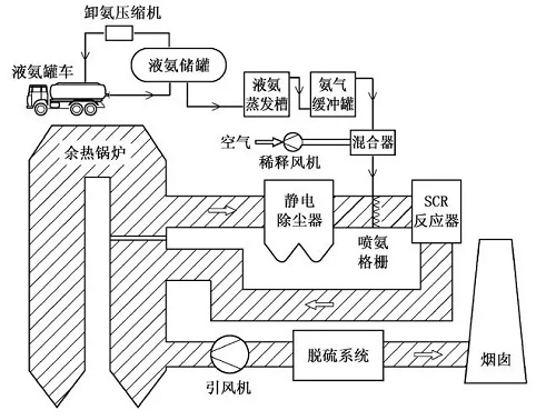
Figure 1 Flow chart of a typical SCR process system in a glass factory
2.1 ammonia storage and transportation system
The physical properties of ammonia: colorless transparent liquid, irritating odor, very soluble in water, toxic, can burn and explode under certain conditions, and can be easily found when leaking. In the national current standard GB18218 "Dangerous Chemicals Major Hazard Source Identification" major hazard source determination, the critical amount of ammonia used in the SCR process is 10t. In the current national standard GB50016 "Code for Fire Protection of Building Design", the fire hazard of ammonia is Class B, and its explosion limit range is 15.5% to 25%. In case of fire, static electricity, etc., it can cause an explosion. Ammonia has a high volume expansion coefficient, and super-filled liquid ammonia storage tanks, gas cylinders, etc. are prone to explosion. Therefore, in the design, construction and use of ammonia storage and transportation systems, safety factors must always be placed first.
The function of the ammonia storage and transportation system is to treat liquid ammonia into ammonia gas with a certain pressure range suitable for the SCR process system. The ammonia storage and transportation area includes process devices such as unloading, storage, evaporation, buffering, transportation and accident discharge. The majority of the ammonia in the SCR process system is here, which is the top priority of fire safety.
2.1.1 Safety spacing
Basic configuration of ammonia storage and transportation area: ammonia compressor for unloading, liquid ammonia storage tank, ammonia transfer pump, liquid ammonia evaporator, ammonia buffer tank, liquid ammonia dilution tank, wastewater treatment system, fire sprinkler system and control room, Distribution room, etc.
The number of liquid ammonia storage tanks is generally 2 to 3 depending on the size of the glass factory. The storage capacity is required to meet the requirements of 7 to 10 days. The above-mentioned horizontal storage tanks are used, and the storage tanks should be arranged in groups within the same fireproof levee. The effective volume in the fire dam is greater than the storage capacity of the main one. The height of the general fire dam should be 1.0m, corresponding to the fire dam. Set the entry and exit steps on both sides. The ammonia area should be provided with a awning of sufficient height and coverage to prevent the summer sun from affecting the temperature rise of the liquid ammonia storage tank. The ammonia storage and transportation area shall be provided with an annular fire lane with a clear width and a net height of 4 m. At least two annular fire lanes shall be connected to the roads within the factory. At the same time, in the storage tank area, the control room, etc. should be equipped with fire-fighting equipment such as portable fire extinguishers. At present, small-scale glass production lines have been discontinued in the process of eliminating backward production capacity in previous years. Domestic glass production enterprises are basically enterprises above designated size. There are more than two float production lines in the factory, and the liquid ammonia tank in the factory. The total capacity of the district is generally 50-200m3, and the fire hazard in the ammonia zone is classified as Class B. The walls, columns, roofs, etc. of the buildings should be made of non-combustible materials. The fire-proof spacing requirements of various parts in the ammonia zone are shown in Table 1. . In addition, at the beginning of the design of the general plan of the glass factory, the general map positioning of the ammonia storage and transportation area should be considered in a comprehensive manner, and should be arranged on the windward side of the glass factory at a lower frequency throughout the year. The ammonia area should be placed away from possible
The workshops or installations that produce fires must have convenient traffic conditions to facilitate the entry and exit of fire-fighting vehicles and evacuation of personnel.
2.1.2 Project examples
Taking a 2×800t/d float glass production line in China as an example, the design and layout of the ammonia area will be specifically explained. The arrangement of the ammonia storage and transportation area is shown in Figure 2. The safety distance between the equipment in the area, the fire road, the tank area and the surrounding buildings. Fire spacing, etc. should meet the requirements of Table 1.
Table 1 Fire separation distance of ammonia storage and transportation area/m
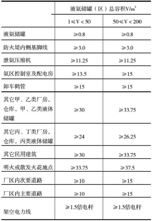
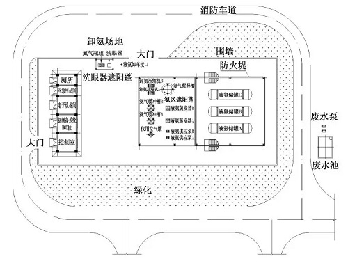
Figure 2 Schematic diagram of liquid ammonia storage and transportation area in glass factory
2.2 fire sprinkler
The fire sprinkler system is the basic guarantee for the safe operation of the ammonia storage and transportation area. It must be placed in the first place in safety production. The fire sprinkler system should cover the liquid ammonia storage tank area, the liquid ammonia evaporation buffer area and the unloading area, and the system spray intensity and The duration is in accordance with the current national standard GB50084 "Design rules for automatic sprinkler systems", GB50219 "Design specifications for water spray fire extinguishing systems". In the ammonia control room, fire automatic alarm device and fire control device should be set up, and communication with the glass factory fire control center can be made. The alarm and control signals can be controlled in the ammonia control room or in the fire control center. When the ammonia area detects that the ammonia content in the air exceeds the limit or there is a fire signal, the system should immediately sound and light alarm, and start the spray system in a chain. In addition, the manual operating device should be set in a safe position. For the larger ammonia storage and transportation area, the fire sprinkler system should be set up in zones, and the deluge valve group should be set separately in each zone to make the control more flexible and avoid waste of water resources. For enterprises in the northern region, anti-freezing measures should be taken for the above-ground fire-fighting pipelines and pipelines located in the frozen soil layer. Generally, electric heat tracing or pipeline heating devices can be used.
In this example, a water spray fire extinguishing system is provided in the ammonia storage and transportation area, and the system has the function of absorbing ammonia gas leaking into the air. Division of protection zone: The liquid ammonia storage tank is divided into one zone vertically, the liquid ammonia evaporation and the buffer zone are one zone, and there are two protection zones. The water spray system start control is divided into three modes: automatic control start, manual remote control start and emergency start. Fire extinguisher configuration: portable ammonia phosphate dry powder fire extinguisher in liquid ammonia evaporation zone and tank area; portable ammonium phosphate dry powder fire extinguisher and carbon dioxide fire extinguisher in electric control room, when the fire extinguisher is set outdoors, there should be corresponding protective measures. The fire plane layout of the SCR liquid ammonia storage and transportation area in this example is shown in Figure 3, and the water spray fire protection system is shown in Figure 4.
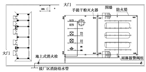
Figure 3 Ammonia fire protection floor plan
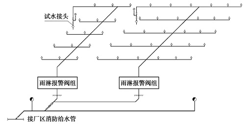
Figure 4 Water spray fire system diagram
In addition, the liquid ammonia storage tank should also be designed to cool the spray pipeline in summer. It is especially important in the southern region. In summer, the high temperature, liquid ammonia storage tank is easy to over temperature and overpressure, causing the safety valve to act, resulting in alarm of ammonia concentration alarm device. Fire sprinkler system action. Therefore, the liquid ammonia storage tank should be equipped with a cooling and cooling system to interlock with the temperature transmitter and pressure transmitter installed on the liquid ammonia storage tank. When the temperature or pressure exceeds the limit, the sound and light alarm is triggered, and the chain starts. The water spray cooling solenoid valve is opened to cool down the storage tank. The general alarm temperature is set to 40 ° C and the alarm pressure is set to 1.45 MPa. In addition, the manual operating device should be set in a safe position.
The drainage in the liquid ammonia dilution tank and the drainage of the fire protection system are strictly prohibited from being directly discharged into the drainage system of the plant. They should be discharged to the wastewater collection tank and discharged into the drainage system after passing the treatment.
2.3 Nitrogen replacement
All containers and pipelines in the ammonia storage and transportation area shall be provided with nitrogen replacement interface. Before the equipment is first put into use, equipment maintenance, equipment shifting and unloading, etc., nitrogen must be used to replace the residual ammonia of the system to ensure personnel and equipment. Safety. In the ammonia area, a sufficient amount of nitrogen bottle should be stored in a safe area, and the pressure of the bottle group should be checked every week. If the pressure is insufficient, it should be replaced in time. Nitrogen replacement should ensure that the ammonia and air mixture in the equipment is below its explosion limit and should generally be less than 5%.
2.4 chain alarm
Ammonia gas leakage alarm should be set in the ammonia storage tank area and ammonia evaporation buffer zone. Smoke detectors should be installed between the control room and the electronic equipment. The arrangement should be in accordance with the national current standard GB50116 "Fire Automatic Alarm System Design Specification". The alarm device is a vital part of the fire safety system. Glass companies should purchase well-known enterprise products with good quality and high precision, and should check them regularly. The system must be approved by the safety and fire department and passed the inspection and acceptance.
The ammonia leak detector should be placed under the ammonia area awning and set according to its monitoring radius. Generally, when the concentration of ammonia in the air reaches 100×10-6, it should be able to automatically send out an alarm signal to interlock the fire sprinkler system. In this example, in order to ensure safety and timely detection of ammonia leakage, an ammonia gas leak detector is installed at five points in the ammonia zone, and the ammonia zone monitoring point arrangement is shown in Fig. 5.
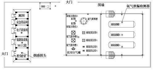
Figure 5 Ammonia zone monitoring point layout
3 Prevention and monitoring of ammonia escape
The ammonia gas from the ammonia storage and transportation area is transported to the ammonia dilution device through the pipe network of the plant, and is mixed with the dilution fan to a certain concentration of ammonia gas, then injected into the flue gas through the nozzle inside the flue, and enters the mixing device, The flue gas is thoroughly mixed and then enters the catalytic reactor to participate in the denitration reaction. In order to achieve better denitration effect, two requirements must be met: first, the catalyst should have sufficient activity, and second, provide a sufficient amount of reducing agent to participate in the reaction. Therefore, there is always an excess of ammonia in the system that does not participate in the reaction and is discharged with the flue gas. This phenomenon is called ammonia escape. Ammonia escape can cause many unfavorable factors, which can lead to fouling of downstream flue and equipment, and it is extremely difficult to clean, pollute the atmosphere, and corrode downstream equipment. When the activity of the catalyst is reduced, it is necessary to inject more ammonia into the reaction, resulting in an increase in ammonia slip. The recovery time of the catalyst should be determined by detecting the amount of ammonia slip, and the new catalytic reactor should be replaced in time to ensure comparison. Low ammonia escape rate generally requires ammonia slip rate to be controlled within the range of (2~4)×10-6.
At present, for the detection of ammonia escape rate, in addition to the commonly used laser gas analyzer, there is an effective method called the extraction method. The principle is to use a high-temperature pumping device to extract a certain volume of flue gas from the flue gas after denitration, so that After the flue gas is sufficiently contacted with water, the ammonium ion concentration in the aqueous solution is measured, and the actual value of the ammonia slip can be obtained by converting the concentration. This method is not affected by dust, temperature and pressure fluctuations in the flue, and the accuracy is high.
4 Conclusion
In addition to the above, in the dilution device of ammonia gas, ammonia injection device and ammonia gas and flue gas mixing device, sufficient safety measures should be taken to maintain sufficient safety spacing and fireworks are strictly prohibited. In particular, the ammonia pipeline should ensure sufficient safety distance when it is laid together with other pipelines. The valves and instruments of the ammonia system should also use ammonia-specific products. In addition, from the perspective of safety and economy, when the glass enterprise adopts the ammonia decomposition hydrogen production process, the hydrogen station should share the ammonia storage and transportation system with the SCR system, which can save floor space and reduce safety hazards.
Metal Sunglasses,Polarized Sun Glasses,Double Rim Sunglasses,Double Bridge Metal Sunglasses
Wenzhou Joysee Eyewear Company Ltd. , https://www.joysee-glasses.com